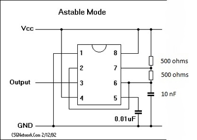
555 Astable

|

|

|
|
These graphics show the different schematics that the 555 timer can be used in.
These are the different breadboards we made using the 555 timer using two 10k ohms resistors and a 0.024uf capacitor.
|
|
|
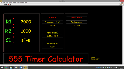
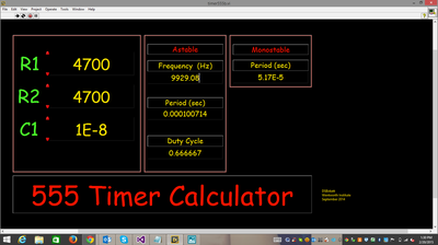
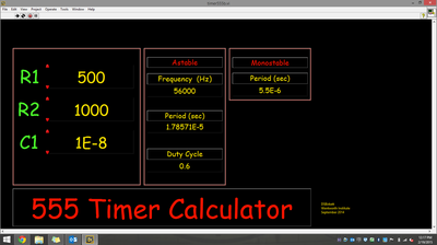
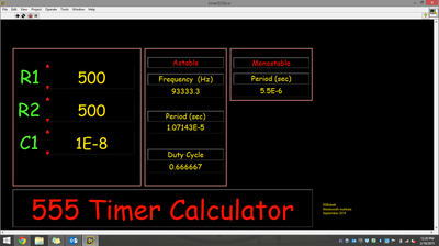
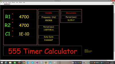
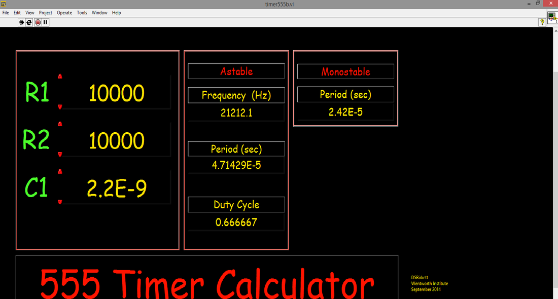
These graphics show the different 555 timer calculators we used to figure out frequency, period, and duty cycle by inputting R1, R2, and C1.
|

|
|
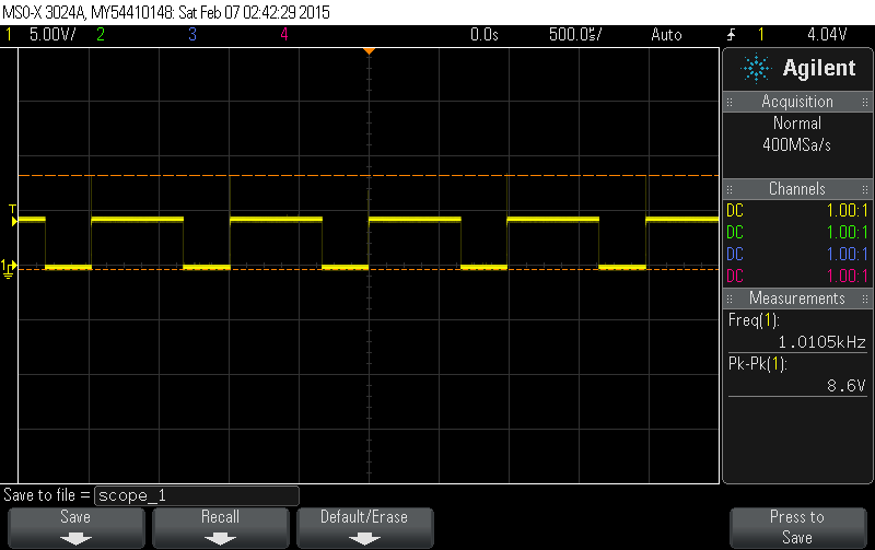
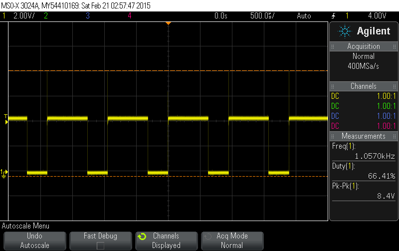
This is the output of the circuit we made with the 555 timer on the oscilloscope.
